6 October 2026
How Ceilometers Work: The Core Technologies Explained
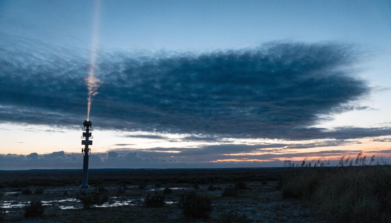
Key takeaways
- The core measurement is time of flight: a laser pulse is fired upward and the time it takes to return from the cloud base is converted directly into a height.
- Millimetre-wave radar is often used alongside lidar because it penetrates rain and snow far better than a laser beam.
- Getting a clean reading requires substantial signal processing to filter out sunlight, dust and false returns before a cloud height can be reported.
- Modern ceilometers output data over standard interfaces such as Modbus TCP or MQTT, so the reading can be integrated into wider monitoring systems.
A ceilometer looks simple from the outside, a sealed unit pointing skyward, but the path from a laser pulse to a displayed cloud height involves several distinct engineering stages. This article walks through the main ones in order.
Time of flight: the basic physical principle
The fundamental measurement behind every lidar ceilometer is time of flight. A laser pulse is emitted straight up, some of that light scatters back off the base of a cloud layer, and the instrument's detector picks up the returning photons. Because light travels at a known, fixed speed, the height of the reflecting layer is calculated directly from the round-trip time using the relationship H = c × Δt / 2, where c is the speed of light and Δt is the time between emission and detection. A cloud base of 10km, for example, corresponds to a round trip of roughly 66.7 microseconds. This is the same basic principle used in other lidar applications, just applied vertically rather than horizontally.
The laser and receiver optics
Most commercial ceilometers use a semiconductor laser operating around the 1550nm wavelength, chosen because it is eye-safe at the power levels involved, in line with IEC 60825 laser safety standards, and because it is less affected by atmospheric scattering than shorter wavelengths. Pulses are fired at a high repetition rate with a narrow beam divergence, so the beam stays tightly focused as it travels upward. On the receiving side, a telescope collects the faint returning light and focuses it onto a highly sensitive detector, commonly an avalanche photodiode or a photon-counting detector, capable of registering individual returning photons from thin or high cloud where the signal is very weak. A narrowband optical filter sits in front of the detector to block out sunlight and other stray light that would otherwise swamp the faint laser return.
Millimetre-wave radar as a complementary technology
Where lidar struggles, in heavy rain, snow, or dense fog, millimetre-wave radar takes over. Operating typically at 35GHz or 94GHz, radar wavelengths are far longer than a laser's, which makes them much less susceptible to attenuation by precipitation. Radar detects cloud particles through Rayleigh scattering, where the strength of the returned echo relates to the size and concentration of the particles in the beam's path. Because radar and lidar have complementary strengths, and complementary weaknesses, combining the two using data fusion techniques such as Kalman filtering gives a more reliable reading across a wider range of weather conditions than either technology alone.
Filtering out noise before a height is reported
The raw returning signal is not clean. Sunlight, ambient city lighting, dust, insects and even birds can all create false returns, and adjacent pulses can overlap in a way that blurs the actual cloud signal. Ceilometers apply several layers of signal processing to deal with this: adaptive thresholding to filter out background light, deconvolution algorithms to separate overlapping returns, and morphological filtering to strip out narrow noise spikes that do not match the expected shape of a genuine cloud return. Only after this processing is a sliding-window peak search applied to identify the actual cloud base height from what remains.
Cloud type classification
Once a clean return is available, some instruments go a step further and attempt to classify the type of cloud present, based on characteristics such as layer thickness and return shape (a thin stratus layer and a tall cumulus cloud produce very different signal profiles). Deep learning models, typically convolutional neural networks trained on large labelled datasets, are increasingly used for this classification step and can reach high accuracy against standard cloud categories.
Keeping the optics and timing accurate
Outdoor optical instruments need active protection to stay accurate. Thermoelectric cooling keeps the laser's output wavelength stable despite ambient temperature swings, and heating elements keep internal components above a safe minimum temperature in cold climates. Precise timing is essential too, since the whole height calculation depends on accurately measuring a delay measured in microseconds, so high-end systems use GPS-disciplined clocks to keep timing synchronised to within a few nanoseconds.
Getting data out of the instrument
A ceilometer is only useful if its data reaches the system that needs it. Industrial units commonly support standard interfaces such as Modbus TCP, HTTP APIs, or MQTT, alongside meteorological-specific formats like WMO BUFR encoding for feeding directly into national weather databases. Buyers building a wider monitoring network should check which protocols an instrument supports and confirm they match the existing data infrastructure. Our RS485 and Modbus explained glossary page covers the basics of this kind of industrial interface if you are unfamiliar with it.
Where the technology is heading next
Some higher-end lidar ceilometers now also measure Doppler shift, which allows them to derive vertical wind speed alongside cloud height, an approach closely related to the dedicated wind lidar technology used in our 3D scanning Doppler wind lidar. MetSensor UK supplies the ZCL3 ceilometer in the UK, built on the lidar principles described above, and can talk through integration options for a specific project.